5.User portal screen operation

※ Please allow incoming mail for "no-reply@verificationemail.com" and "no-reply@rms.i-pro.com" in advance.


2.
Click the [Sign up] button.
3.
Confirm the contents of End User License Agreement, check [I agree], and click the [Next page] button.
After confirming End User License Agreement by operating the scroll bar, you can check [I agree].
4.
Enter a received e-mail address into the e-mail address, set the password and name, and click the [Register] button.

* Do not include all or part of the user name or e-mail address in the password, or use words or meaningful characters. You may be guessed by a third party and be logged in by impersonation.


* Do not use the same password on multiple systems.


5.
A confirmation e-mail is sent to the registered e-mail address. Click the e-mail link destination after receiving.
You can log in to the remote monitoring service by completing your enrollment. Be sure to complete the user registration within 24 hours after receiving the e-mail.
6.
When user registration is completed, the following screen is displayed. Return to the login screen and login with the registered account.
1.
Visit the login site (https://rms.i-pro.com) in your browser.
The user who logs in can be selected from "Subscriber (registering as a service by yourself)" or "Shared user".

* "Shared users" are users other than the subscriber who can view live images and recorded images on the portal screen.


[If the user who logged in chooses "Subscriber (register for service by yourself)", please proceed here.]
2.
In the "E-mail address" and "Password" fields, enter the e-mail address and login password registered at the time of the remote monitoring service contract, and then click the [Log in] button.
The portal screen is displayed.
If a login fails more than once, a lockout occurs for up to 15 minutes. You will not be able to log in during lockout.
[If the user who logged in chooses "Shared user", please proceed here.]
1.
In the "E-mail address" and "Password" fields, enter the e-mail address and login password in the e-mail sent when you invited to the service, and click the [Log in] button.

* The e-mail is sent automatically when the subscriber adds a shared user.


* If a login fails more than once, a lockout occurs for up to 15 minutes. You will not be able to log in during lockout.


2.
Enter the login password listed in the initial password email in the "Password" and "Confirm new password" fields, and click the [Change] button.
The portal screen is displayed. You do not need to change the password after the second login.

* Do not use all or part of the e-mail address registered in the login password, or use words or meaningful characters. You may be guessed by a third party and be logged in by impersonation.


* Do not use the same password on multiple systems.


* Do not use all or part of the registered e-mail address as the login password.


[When a user who has set up two-step verification logs in]
If you are using app authentication and need to change your smartphone model, please be sure to follow the procedure for changing your app model to transfer the app. If the reconfiguration fails, please refer to [If you can no longer use two-step verification] and initialize the two-step verification.
If you have set up two-step verification, you will need to enter an authentication code when logging in. However, if you have logged in at least once with device authentication turned on, you will not need to enter an authentication code when logging in using that device.

*If you turn on device authentication, you will not need to enter an authentication code when logging in using the same browser with the same account.


*You can set up to 10 devices for device authentication.


1.
In the "Email address" and "Password" fields, enter the email address and login password registered to the i-PRO Remo. Service, and then click the [Login] button.
If you have set up app authentication
2.
Please check the authentication code in the authentication app, enter the authentication code in the two-step authentication dialog, and then click the [Submit] button.
The portal screen will be displayed.
If you have configured email authentication
2.
A verification code will be sent to your registered email address. Please check your email, enter the verification code in the two-step verification dialog, and then click the [Send] button.
Please enter the authentication code within 3 minutes after the authentication dialog is displayed.
The portal screen will be displayed.
If you can no longer use two-step verification
2.
Please click the [Click here for those who can no longer be certified in two steps] button in the two-step verification dialog.
3.
After entering your email address, click the [Send] button.
You will receive an email titled "Please set two-step authentication" to the email address you entered.
4.
Access the URL specified in the email.
Two-step authentication initialization is complete. After two-step authentication initialization, the authentication setting will be set to [none]. If you want to set up two-step verification again, return to the login site, log in with your email address and login password, and then set up two-step verification.
[If you will use Google account]
When setting up single sign-on for the first time

1. Click "Log in with Google account" from the login screen.


2. Select or input your Google account.


3. If you input your Google account in step 2, please input correct password for Google account.


4. The "First account link" screen will be displayed. Enter the email address and password for Remote Monitoring account you want to link, and then click the "Link" button.


5. Once the connection is complete, you will be logged in with Remote Monitoring account entered in step 4, and the camera list or favorites screen will be displayed.


If you have already set up single sign-on
If you select "Log in with Google account" from the login screen, you will be automatically logged in and the camera list or favorites screen will be displayed.
To cancel single sign-on settings

1. From the user menu, select "Confirm / cancel SSO account"


2. On the "Confirm/Unlink account Linking" screen, select "Unlink".


3. Enter your Remote Monitoring password and select "Yes".


Log out of the remote monitoring service.
1.
Click the user icon to display the menu bar, and click the [Log out] button.
2.
Click the [Yes] button.
To not log out, click the [No] button. The "Confirm" window closes.
The login screen is displayed.
If you forget your login password, reset your login password.
1.
Click [Forgot your password?] on the login screen.
2.
In the "E-mail address" entry field, enter the e-mail address registered at the time of remote monitoring service contract or when adding users, and then click the [Send] button.
The e-mail with "Verification Code" and "Please set new password" is delivered to the entered e-mail address.

* If you do not want to reset the login password, click the [Return to login screen] button. The Initialize Password screen closes.


* If the e-mail does not arrive, check that the entered e-mail address is correct and that it is not in the spam folder.


3.
The URL specified in the "Notice of Initialization of Password" email is accessed.
4.
Enter the new login password in the "New password" and "Confirm the password" fields, enter the authentication code for registration in the "Authentication Code for Registration" field, and click the [Change] button.
The login password is reset and you are returned to the login site.

* Do not use all or part of the e-mail address registered in the login password, or use words or meaningful characters. You may be guessed by a third party and be logged in by impersonation.


* Do not use the same password on multiple systems.


* If you do not want to reset the login password, click the [Return to login screen] button. The Change Password screen closes.


If the "Reset Password" screen in step 4 does not appear, start again from step 1.
Change the login password.
1.
Click the user icon to display the menu bar, and click the [Change password] button.
2.
Enter the current login password in the "Password" input field, enter the new login password in the "New password" input field and the "Confirm the password" input field, and click the [Change] button.
The login password is changed.

* Do not use all or part of the e-mail address registered in the login password, or use words or meaningful characters. You may be guessed by a third party and be logged in by impersonation.


* Do not use the same password on multiple systems.


* If password leakage is suspected, change the password immediately.


* To not change the login password, click the [Cancel] button. The "Change password" window closes.


* If you are using i-PRO Mobile APP (mobile application), please register your e-mail address and password again in the Web service registration screen of the mobile application after changing the password.


To change mail addresses
1.
Click the user icon to display the menu bar, and click the [Change email address] button.
2.
Enter the e-mail address to be changed and the password of the logged-in user in the input field, and click the [Change] button.
"Change your email address" is delivered to the entered e-mail address.
3.
The URL specified in the e-mail of "Change your email address" is accessed.
The e-mail address change is completed.

* After you complete the email address change, you can log in to the remote monitoring service with the new email address. Please complete changing your e-mail address within 24 hours of receiving the e-mail.


* If you are using i-PRO Mobile APP (mobile application), please register your email address and password again in the Web service registration screen of mobile application after changing your email address.


To change color scheme.
1.
Click the user icon to display the menu bar, and click the [Theme setting] button.
2.
Click on the color scheme you want to change.
If you change your e-mail address on the remote monitoring service, if you are using the i-PRO Mobile APP (mobile application), you will need to delete the connection with the mobile device once and register your e-mail address and password again on the Web service registration screen of the mobile application.
1.
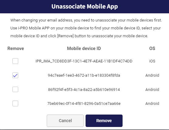
Click the user icon to display the menu bar, and click the [Unassociate Mobile APP] button.
2.
The linked mobile device ID is displayed. Select the mobile device to be deleted, and click the [Remove] button.

* To check the ID of mobile devices using the mobile application, go to [Settings] → [Notification Settings] → [Mobile Device Info] → [Mobile Device ID] in the mobile application.


3.
The following message is displayed. Confirm that the ID is the mobile device to be linked and deleted, and then click "Yes".
The connection with the mobile device is deleted.
After deleting the connection with the mobile device, register the e-mail address and password again on the Web service registration screen of the mobile application.
If you have performed app authentication and need to change your smartphone model, please be sure to transfer the app according to the procedure for changing your smartphone model. If the re-setting fails, [If you can no longer use two-step verification] and then initialize two-step verification.

*The screen image may differ from the actual screen.


1.
Click the user icon to display the menu bar and click the [Two-step verification settings] button.
[When setting up App authentication]
2.
In your current two-step verification settings, select "App Authentication" and click the "Change" button.
3.
Please have your authentication app ready, click the [2D code display] button, and scan the 2D code with the authentication app.
We recommend using the authentication app "WinAuth" or "Authy."
2D code can be displayed for up to 5 minutes.
Please do not close the two-step authentication setting dialog until the settings are complete. If you close the dialog before completing the settings, you will need to re-scan 2D code.
4.
After entering the authentication code displayed in your authentication app, click the [Send] button.
5.
A dialog box will appear indicating that two-step verification has been completed.
[To set up email authentication]
2.
In the Current two-step verification Settings, select "Email certification" and click the "Change" button.
3.
A dialog box will appear indicating that two-step verification has been completed.
[Disabling two-step verification]
2.
In the Current two-step verification setting, select [None] and click the [Change] button.
3.
A dialog box will appear indicating that two-step verification has been completed.
You can change the region of streaming server for WebRTC (P2P) connection. Default region is Frankfurt.
By changing the region, you can show video more smoothly.

*The screen image may differ from the actual screen.


(1)
Click the user icon to display the menu bar and click the [Change streaming server] button.
(2)
Select the nearest server from pull-down menu.
(3)
Click [Change] button.
If the video is not displayed, restart the recorder or camera.

* When you connect camera via recorder, restart the recorder.


* When you connect camera directly, restart the camera.


When viewing video on a smartphone or tablet, we recommend using the i-PRO Mobile APP (mobile application).
1.
Visit the login site (https://rms.i-pro.com) in your browser.
The live image is displayed on the portal screen.
(1)[Search cameras]
Searches for the displayed cameras by camera name, and narrows down the display.
(2)[Display Info]
The information is displayed according to the display status of the live image.

* "Displaying JPEG Images" is displayed.


Up to 40 cameras can be displayed on the camera list screen. However, if there are 13 or more cameras or if you are using iPhone, iPad, Android, an JPEG is displayed. The image is updated every 30 seconds.

* "Reduced frame mode" is displayed.


When multiple screens are displayed, the resolution and frame rate of the displayed camera are automatically adjusted according to the number of cameras displayed. If you are viewing video from the same camera on another device or in another browser, the resolution and frame rate are not automatically adjusted. The displayed frame rate will then be 1fps.
(3)[Image resize bar]
By moving the bar, you can change the size of the displayed image to small, medium, or large.
(4)[Full screen]
You can view the screen in full screen.
To exit full screen, click the [Exit full screen] button at the upper right of the screen or click the [Esc] button on the keyboard.
(5)[Privacy guard switch button]
You can switch the display of the camera with privacy guard ON and the camera with privacy guard OFF. Displayed when a camera with Privacy Guard is registered.
Also, for cameras with privacy guard enabled, the following icon is displayed at the beginning of the camera title.

*Privacy guard ON


*Privacy guard OFF


(6)[Message icon]
If there are unconfirmed messages that have been notified, the number of unread messages will be displayed. You can check the details of the message by clicking it.
If [Email Notification] of permission settings is turned off for shared users, [Message history] and [Maintenance history] will not be displayed. Please refer to 4.3.4 Set permissions for more information about permission settings.
(7)[Alarm notification icon]
If there are unacknowledged alarms that have been notified, the unread count is displayed. You can check the details of the alarm by clicking it.
When viewing video on a smartphone or tablet, we recommend using the i-PRO Mobile APP (mobile application).
1.
Visit the login site (https://rms.i-pro.com) in your browser.
The live image is displayed on the portal screen.
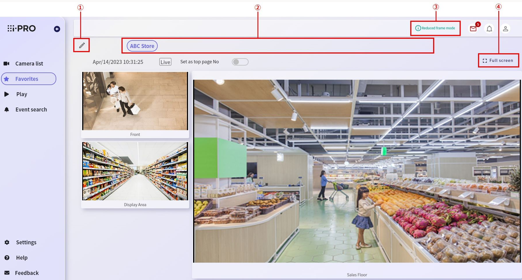
(1)[Edit button]

Edit the favorite group. For details on how to edit favorite groups, refer to 5.5 Favorite settings
(2)[Favorite groups]
The created favorite groups are displayed. When you select a favorite group, the selected group is displayed in the image display area.
(3)[Display info]
The information is displayed according to the display status of the live image.

・"Displaying JPEG Images" is displayed.


Up to 40 cameras can be displayed on the camera list screen. However, if there are 13 or more cameras or if you are using iPhone, iPad, Android, an JPEG is displayed. The image is updated every 30 seconds.

* "Reduced frame mode" is displayed.


When multiple screens are displayed, the resolution and frame rate of the displayed camera are automatically adjusted according to the number of cameras displayed. If you are viewing video from the same camera on another device or in another browser, the resolution and frame rate are not automatically adjusted. The displayed frame rate will then be 1fps.
(4)[Full Screen]
You can view the screen in full screen.
To exit full screen, click the [Exit full screen] button at the upper right of the screen or click the [Esc] button on the keyboard.
Available only for Windows and Android browsers.
1.
Visit the login site (https://rms.i-pro.com) in your browser.
The live image is displayed on the portal screen.
2.
Click the camera image.
The single image of the selected camera is displayed, and the live image is displayed.
When the Favorites screen is displayed, clicking the image on the camera will switch to the single screen.
(1)[Live video display/digital zoom]
The live image of the selected camera is displayed.
You can also perform digital zoom by operating the wheel on the screen. After digital zooming, click centering is available.
Optical zooming is available for PTZ cameras. For details on operating the PTZ camera, refer to the next section, 5.3.5 Operate PTZ cameras
(2)[Volume button]
You can change the volume of the camera microphone.
When you mouse over the volume button, the volume adjustment bar appears, allowing you to adjust the volume of the microphone.
You can also turn mute on/off by clicking the icon.
(3)[Brightness button]
You can change the brightness of the camera image.
When the mouse is over the brightness button, the brightness adjustment button is displayed and the brightness of the camera image can be adjusted.
The [+] and [-] buttons can be held down. In addition, by clicking the [Reset] button, you can immediately change the brightness of the standard set in the camera.
(4)[AUX button]
Displayed on cameras that have AUX set as the terminal.
When you hover your mouse over the AUX button, the AUX OPEN/CLOSE switching button will be displayed, and you can switch the status by clicking the button (the button name will be displayed as the name set on the camera).
(5)[Full screen]
You can view the screen in full screen.
When displaying a full screen, the camera's playback control buttons and volume/brightness buttons are displayed only when hovering.
To exit full screen, click the [Exit full screen] button at the lower right of the screen or click the [Esc] button on the keyboard.
(6)[Display info]
The information is displayed according to the display status of the live image.

* "Reduced frame mode" is displayed.


For cameras with resolutions larger than Full HD, the resolution and frame rate are adjusted automatically.
For information on playing back recorded images on a single screen, refer to 5.4 Playback and download recorded images

* The camera operation buttons are displayed when the mouse is over at the bottom of the image.


* Brightness can be adjusted only while a live image is displayed.


* If you change the brightness of the camera, the brightness of the video to be recorded is also changed and displayed.


* Depending on the communication environment, time lag may occur when operating the camera.


(7)[Device tree]
Selecting a camera, you can switch the camera displayed on a single screen.
(8)[Audio output]
If a speaker is connected to the camera, you can start transmitting audio.
(9)[Copy URL button]
Copy the URL to this screen to your clipboard.

* Single sign-on (SSO) is required to log in.
Please refer to "5.2.1 Log in (When setting up single sign-on for the first time)" for instructions on how to configure SSO.


If a speaker is connected to the camera, you can transmit audio. To use the audio transmission function, the camera's "Audio transmission mode" must be set to "Audio output(From PC)", "Interactive(Full-duplex)" or "Interactive(Half-duplex)".
Click the audio output button on the screen to start transmitting audio. While transmitting audio, the button turns blue and the remaining time (in seconds) for transmission is displayed. Clicking the transmission button again will end audio transmission. Audio transmission will also end automatically when the remaining time for transmission reaches 0 seconds.

* The following firmware versions are required to audio output.


  When using Recorder
 NX series: Ver. 1.30 or later
 NU series: Ver. 1.50 or later


  When using Camera
 New X-series: Ver. 3.40 or later
 Other series: Ver. 2.80 or later
 *For details, please check the release notes for the firmware/software for the camera.


* You cannot move to recording playback while transmitting audio. You also cannot switch cameras.


* This service is not available to shared users without permission


* If you reload the browser page, close the tab, log out, or close the browser while transmitting audio, you will not be able to continue transmitting audio. Please note that you will also not be able to resume transmitting audio for a while


* You will not be able to start transmitting audio if someone else is transmitting audio


* If the audio is interrupted, change the camera's "Transmission Interval" to 320 ms or more.


* If you are using a direct camera connection, make sure that the camera's [HTTP Port Number] setting is set to "80".


You can adjust the horizontal/vertical position (pan/tilt) and optical zooming of the PTZ camera. You can also change or register the preset position.

* The PTZ can be used only while a live image is displayed. You cannot operate during playback.


* When using 360-degree fish eye camera with Single or Quad PTZ, you can control Pan, Tilt, Zoom on each screen.


* When using a mobile device, you can only move presets and edit preset names (Pan, Tilt, Zoom and Preset cannot be registered).


* With some ONVIF cameras, you may not be able to operate PTZ depending on the model. At that time, digital zoom operation of live video cannot be performed.


If your camera is capable of pan and tilt operations, an arrow icon pointing in a moveable direction will appear when hovering over the image. By holding down the left mouse button, you can pan and tilt in the direction of the arrow.
The illustration below shows an arrow icon when it can be moved diagonally to the lower left.
If you can register or set a preset with your camera, the preset setting screen will appear as shown in the red frame below when hovering over the video.
For ONVIF cameras, the preset setting window is not displayed.
PTZ cameras can be operated only in single-image mode.
To display a single image, follow the procedure below.
1.
Visit the login site (https://rms.i-pro.com) in your browser.
The live image is displayed on the portal screen.
2.
Select the PTZ images you want to operate.
The operation screen of the selected camera is displayed.
Clicking the position you want to make the center of the angle of view moves the camera's orientation to the position where you clicked.
You can also move the camera image gradually by pressing and holding on the screen.
Press and hold a point away from the center of the screen to move the camera quickly.
The black bars that are not on the image are excluded from click detection.
You can adjust the zoom by using the wheel on the screen.
The upward-facing wheel zooms in to the telephoto and the downward-facing wheel zooms in to the wide-angle.
You can also use drag and zoom on the screen.
When you mouse over the focus button, the focus adjustment button is displayed.
The [Far] and [Near] buttons can be pressed for a long time, and [Auto] can be adjusted automatically with a single click.
By registering an angle of view (preset) as the home position to be checked carefully, you can move the camera in an instant.
The home position is the first preset in the list. To register a home position, follow the procedure in "Registering a Preset" below for the first preset in the list.
1.
Hover over the single-screen image area.
The preset setting screen is displayed.
2.
Click the [Home] button.
The camera orientation moves to the angle of view registered as the home position.
By registering a specific angle of view (preset) in advance, you can move the camera in an instant.
For details on registering a preset, refer to 5.3.11 Register a preset in the next section.
1.
Hover over the single-screen image area.
The preset setting screen is displayed.
2.
Click the part where the preset name is displayed, and select the preset you want to move from the list.
The camera orientation moves to the angle of view of the selected preset.
By registering a specific angle of view (preset) in advance, you can move the camera in an instant.
Up to 10 presets can be registered.
Presets cannot be registered if [ Settings (Camera Settings) ] in the permission settings is turned off. For details on permission settings, please refer to 4.3.4 Set permissions.
1.
Hover over the single-screen image area.
The preset setting screen is displayed.
2.
Click the part where the preset name is displayed, and select the preset for which you want to register the angle of view from the list.
3.
Operate the mouse on the image to set the angle of view to be registered. For details on how to operate the angle of view, refer to 5.3.6 Adjusting the horizontal position and vertical position (Pan and Tilt) and 5.3.7 To adjust the zoom factor in the previous section.
4.
Click the [Register] icon on the preset setting screen.
When a confirmation window appears, click [Yes] to register the preset.
The beginning of the preset list is registered as the home position.
Any name can be registered or changed for the preset.
Presets cannot be registered if [ Settings (Camera Settings) ] in the permission settings is turned off. For details on permission settings, please refer to 4.3.4 Set permissions.
1.
Hover over the single-screen image area.
The preset setting screen is displayed.
2.
Click the part where the preset name is displayed, and select the preset whose name you want to register from the list.
3.
Click the [Edit preset name] button.
The preset name editing screen appears.
4.
Enter the name of the preset you want to change, and click [Yes].
This completes editing of the preset name.
If you are using an old PTZ camera and want to operate PTZ, please try this method.

1. Click the [Forced PTZ operation] button.


2. Click [ON] button.


* Operation is not guaranteed.


* It does not work for non-PTZ cameras.


You can use PTZ control panel if you want to operate pan/tilt and optical zooming of the PTZ camera.
(1)
For PTZ cameras, you can display the operation panel by clicking the [PTZ control] tab.
(2)
You can adjust the zoom magnification. Click the [x1] button to increase the size by 1.0. Press and hold the [-] button to adjust to wide-angle, and press and hold the [+] button to adjust to telephoto.
(3)
Focus can be adjusted. Click the [Auto] button to automatically adjust the focus. The [Near] button adjusts toward the near direction, and the [Far] button adjusts toward the far direction.
(4)
You can gradually move the camera image by long-pressing in the direction you want to move. You can quickly move the camera by long-pressing somewhere away from the center.
(5)
If a sequence operation is registered to the camera, you can start the sequence operation by selecting it from the list and clicking the button. You can also stop it by clicking the button.
(6)
Select a preset name from the list and click the button to move to the preset position. Please refer each section for moving to home position, register a preset and editing a preset name.
Available only in Windows browsers.
Dewarp function applies 3D technique to correcting the fisheye image of omnidirectional cameras, and rotates the image or cuts out the image and displays it on the PTZ.
In the remote monitoring service, you can operate the dewarp function while viewing live and recorded images in the full-heading camera (imaging mode: fish eye) in a single screen.

* The dewarp function can be operated only in a single screen with a full-orientation camera (imaging mode: fish eye).


You can.

* The Dewarp function cannot be operated on the [Favorites] screen.


If your camera is able to operate the dewarp function, the mouse icon changes to a grab icon when hovering over the video.
Operation of the dewarp function can be performed only on a single screen.
To display a single image, follow the procedure below.
1.
Visit the login site (https://rms.i-pro.com) in your browser.
The live image is displayed on the portal screen.
2.
Click the image of the all-directional camera you want to operate.
The operation screen of the selected camera is displayed.
You can rotate an image by dragging the mouse in the direction you want to rotate.
Double-click or wheel upward at the position where you want the center of the angle of view to appear in PTZ view, centered on the position of the mouse.
Double-click or lower wheel on the picture to switch to fish-eye view.
You can turn on or off the dewarp function.
For resolutions higher than 5M, video and audio delays may increase depending on the PC specs. In that case, turn off the dewarp and display the video.
You can use the PTZ manual tracking function while displaying live footage from the radar screen of Security Radar in single screen. To display single screen, follow the steps below.
(1)
Visit the login site (https://rms.i-pro.com) in your browser.
-> Live images will be displayed on the portal screen.
(2)
Click on the radar screen image of Security Radar you want to operate.
-> The radar screen of the selected camera will be displayed.
When you click on the radar screen, the linked PTZ camera will point to the location you clicked.
The PTZ manual tracking function is only available on the radar screen.

For information on how to configure Security Radar, including how to link it with a PTZ camera, please read the instruction manual for Security Radar.

* Available only for Windows and Android browsers.


* When viewing video on a smartphone or tablet, we recommend using the i-PRO Mobile APP (mobile application).


* In case of 360-degree camera (Imaging Mode: Fisheye), you can operate the dewarp function while playing back recorded images on a single screen. For details on operating the dewarp function, refer to 5.3.16 Rotate the fisheye image.


You can playback recorded images from the recorder or camera (which SD card is inserted) connected to the remote monitoring service.

*If the camera is directly connected and no SD card is inserted, the screen below will be displayed and recorded images will not be playable.


1.
Visit the login site (https://rms.i-pro.com) in your browser.
The live image is displayed on the portal screen.
2.
Click the image of the camera you want to playback.
The operation screen of the selected camera is displayed.
(1)[Date and time]
Displays the video date and time of the currently displayed image.
(2)[Timeline]
You can check the recording period and event detection status.
(3)[Calendar]
You can specify the date on which the timeline is displayed from the calendar.
(4)[Scale change bar]
You can change the display scale of the timeline.
(5)[Playback Control]
You can control playback, reverse playback, pause, high-speed playback, high-speed reverse playback, single-frame advance, and reverse frame advance.
When the camera is directly connected and SD card is inserted, you can control play, pause, and fast playback.
(6)[Audio control]
You can adjust the volume of the audio being played back.
(7)[Maximize]
The screen can be maximized for display.

* Video and audio may be shifted by a few seconds depending on the communication conditions and PC loads.


* Up to four cameras can be played simultaneously for one recorder. You may not be able to start playback if it is being played on other devices or browsers.


* When the image format of camera is MJPEG, audio is not available when playing back.


3.
You can playback recorded images by dragging the timeline or clicking where you want to play it.
When you finish dragging or click on the timeline, the recorded image starts playing from the position indicated by the middle video date and time line.
If you connect the camera directly, the recording period will not be displayed, but you can play back recorded images using the same operations if the recorded data exists at that date and time.
Available only in Windows browsers.
1.
Visit the login site (https://rms.i-pro.com) in your browser.
The live image is displayed on the portal screen.
2.
Click the image of the camera you want to playback, then click the [Download videos] button.
The download operation panel is displayed.
(1)[Download videos]
You can show or hide the "Download operation panel".
(2)[Download operation panel]
By specifying the [Start date & time] and the [End date & time] and clicking the [Save] button, you can download recorded images for the specified period.

* Up to 60 minutes can be specified for the download period.


3.
Specify the date and time you want to download, and click the [Save] button.
A dialog box appears to select a destination folder for recorded images.
4.
Select a destination folder for the recorded images and click the [Select Folder] button.
The following dialog box will appear, and then click the [Edit files] button to start the download.

* You cannot navigate to other screens during downloading. To move to another screen, cancel the download.


* If the recording data is divided due to the change of daylight saving time, etc., it may not be possible to download all the video for the specified period.


* The following folder cannot be selected as the destination folder. Please select a subfolder as the destination folder.


- Dowmload
- Desktop
- Document
- C Drive
You can only download from cameras withan SD card inserted.
1.
Visit the login site (https://rms.i-pro.com) in your browser.
The live image is displayed on the portal screen.
2.
Click [Settings] button.
3.
Click [Stream settings] tab.
4.
Select [How to download SD] of [Settings for camera direct connection].
Please refer to Step 7 and beyond for instructions on how to download each.
5.
Click [Main screen].
The live image is displayed on the portal screen.

6.
Click the image of the camera you want to playback, then click the [Download videos] button.
The SD recording data download operation panel is displayed.
When [File unit] is selected as [How to download SD]
7.
Select the date and time data you want todownload and click the [Download] button.
The download starts.

*You cannot move to other screens and perform other operations while downloading.


*If you want to move to another screen, please cancel the download.


When [Date and time] is selected as [How to download SD]
7.
Select [Start date & time] and [End date and time] of the recording you want to download and click the [Apply] button.
A list of recorded images within the search period is displayed.
The SD recording data download screen and the camera log list display screen cannot be displayed at the same time.
8.
Select the date and time data you want to download and click the [Download] button.
The download starts.

* You will not be able to move to other screens during downloading. If you want to move to another screen, please cancel the download.


* Only data displayed on the same page can be downloaded at the same time.


1.
Visit the login site (https://rms.i-pro.com) in your browser.
The live image is displayed on the portal screen.
2.
Click the camera image you want to playback and click [Take a snapshot image] button.
The image displayed on the video panel is downloaded.
The download destination is the download folder set in your browser.
Available only in Windows browsers.
When cameras are registered in the remote monitoring service, images can be displayed as favorite groups at the same time. You can create up to 50 favorite groups.
If the editable area cannot be allocated, the following message is displayed.
"Use a display with a resolution of 1024x768 or more. Otherwise, the editing area may not be secured when displaying the bookmark bar, etc. When this message does not disappear, close the bookmark bar. When a mobile device is used, create a group using a browser for PC. The editing area sometimes can be secured by increasing the magnification of the browser or reducing the size with the display settings of Windows."
1.
Select [Favorites] from the side menu, and click the [Create a group] button.
2.
Enter a title, select a layout, and click the [OK] button.
3.
The creation method varies depending on the selected layout type.
When "4-split", "9-split", "12-split", "16-split" and "30-split" are selected
Click the camera you want to register from the left menu and it will be arranged in order in the right frame. To correct the camera, click the trash icon or uncheck the camera in the left menu and reselect the camera. When finished, click the [Confirm] button.
You can drag and drop aligned camera images to swap them.
When "Custom" is selected
Click the camera you want to register from the left menu to place it in the canvas on the right. By dragging the mouse, you can move or resize it to any position. When you have finished arranging all the cameras you want to register, click the [Confirm] button.
You cannot register multiple identical cameras to the same favorite.
4.
Check the final layout and click the [Save] button if there is no problem. To change it, click the [Back] button. If you want to change the favorite title, you can edit it by clicking the title name.
1.
Select [Favorites] from the side menu, and click the [Edit] button (pen icon).
2.
Click the [Add] button. Following operations are the same as creating a favorite for the first time.
Select [Favorites] from the side menu, and select the favorite you want to view.
If the number of created favorite groups is large, the [All favorites] button and the favorites at the top in the sequence are displayed.
If the favorite button you want to switch to is not displayed, select the [All favorites] button and select a favorite from the favorites tree.
1.
Select [Favorites] from the side menu, and click the pen icon.
2.
Select the name of the favorite to which you want to add a camera from the list of favorites under [Edit the favorites], and click the [Edit] button.
3.
From [Camera selection], click the [>] button.
4.
Depending on the selected layout type, the method of addition varies.
When "4-split", "9-split", "12-split", "16-split" and "30-split" are selected
When you click the camera you want to register from the left menu, it will be arranged in the order of the empty frame on the right. When you finish, click the [Back] button.
You can't add more than the maximum number. For example, if you want to add a camera to a "4-split" layout, change the layout to "9-split", "Custom", etc.
When "Custom" is selected
Click the camera you want to register from the left menu to place it in the canvas on the right. Adjust the layout by dragging the mouse and click the [Back] button.
5.
Click [Save] to confirm.
1.
2.
Click the trash icon in the upper left corner of the thumbnail image of the camera you want to delete.
3.
After completing, click the [Back] button and perform step 5 of 5.5.5 Adding cameras to favorite group.
1.
2.
From [Layout], click [>] button.
3.
Select the layout you want to change and click the [Back] button.
1.
2.
Change the [Favorite title] and confirm by clicking the [Save] button.
1.
Select [Favorites] from the side menu, and click the pen icon.
2.
Click on [Sort and delete].
3.
Drag the drag icon to the left of the favorite name you want to sort, change it to the position you want to replace, and click the [Save] button.
2.
Move the cursor to the name of the favorite you want to delete, then click the trash icon. If there is no problem, click [Yes] to delete it.
You can set the camera included in favorites to be used by shared users.

*For details on creating shared users, refer to 4.1.2 Set up shared users or 4.3.1 Register a shared user.


* Only subscribers can share favorite cameras.


* You cannot share individual cameras or unshare share settings from the Favorites screen.


1.
Select [Favorites] from the side menu, and click the [Share the favorite cameras] icon.
2.
Select the [Sharing] check box of the user who wants to share the camera included in the favorites, and click the "Share" button.
3.
The message "Camera sharing is complete" is displayed, and the settings are completed.
You can change the top screen after login to the favorite screen by clicking the button of [Set as top page]. You can clear it by clicking it again.
This setting is valid for each browser you use.
If you set "Click Centering Operation" on the Favorites screen to "Yes", you can perform click-centering operations without enlarging the image when you click on it, without leaving the Favorites screen.

This means that if you register Security Radar and a PTZ camera linked to Security Radar on the same favorites screen, you can move the PTZ camera simultaneously by performing a click-centering operation on the radar screen.

* This setting is valid for each browser you use.


* Click-centering is not possible when in Full screen mode.


If you select "No" (default setting), you will be prompted to switch to the single image display screen.
1.
Visit the login site (https://rms.i-pro.com) in your browser.
2.
Select [Event search] from the side menu.
The event list is displayed.
(1)[Event image]
Clicking an image changes to a single screen and plays back the recorded video from the event occurrence time. For information on playing back recorded images, see 5.4.1 Playing recorded images (Single screen).
(2)[Page transition]
When there are more than 100 event search results, you can change the page to check.
(3)[Image size change bar]
Move the bar to change the size of the displayed image to small, medium, or large.
If the camera is directly connected and no SD card is inserted, clicking on an image will not transition to a single screen.
1.
Visit the login site (https://rms.i-pro.com) in your browser.
2.
Click the [Alarm notifications] button on the upper right of the portal screen.
The last 10 events are displayed.
(1)[Alarm notifications button]
The last 10 events are displayed.
(2)[Event display]
The occurrence date and time of the generated event, thumbnail, and alarm type are displayed.
(3)[View button]
Display the screen to play recorded video from the event occurrence time.
(4)[To the full list button]
Displays the event search screen.
If the camera is directly connected and no SD card is inserted, [View] button will not be displayed.
The events that can be detected vary depending on the camera model or recorder.
When using ONVIF cameras, all events are classified as Camera Site Alarms.
When an event occurs, a red frame appears around the image of the camera where the event occurred on the camera list screen or favorite screen. If the red frame does not need to be displayed, set to OFF by referring to 4.1.13 Changing event notification settings.
The red frame disappears after about one minute.
In addition, when an event occurs, you can send an email or send an PUSH notification to the mobile app.
In the e-mail, the event type, the device where the event originated, and the date and time when the event occurred are notified.
Clicking the URL that says "To check the details, log in to the remote monitoring service from the URL below" specified in the received email will access the remote monitoring service login site.
To enable this function, click "Change" on the screen displayed by clicking the "Alarm notifications/Error detections" on the portal screen.
The notification setting you want to enable can be set by turning "ON" and clicking "Change". If OFF, e-mail notification or PUSH notification to the mobile app will not be performed.
You can also set the type of event to be notified and the notification time.
If you want to set the type of event to be notified, select the event you want to be notified of from [Events to notify] below.
If you want to set the notification time, select [Schedule] below.

1. Select [Setup] to display the schedule settings screen.


2. Select the time by left-clicking the mouse at the start time and dragging it to the end time.


3. Release the left mouse click at the end time and the [Notification setting] screen will be displayed. On this screen, set whether to send email notifications and push notifications at the specified time. You can also change the displayed start and end times. After changing, press the [Setup] button.


4. Return to the [Notification settings] screen and press the [Change] button to complete the settings.


If you want to set the event name to be notified, select [Custom settings] below.

1. Select [Custom settings] to display the event custom settings screen.


2. When you select [Custom settings], the event custom settings screen will be displayed.


You can set the message ID and event name of alarms notified from cameras and recorder. If you select "Use the setting name on the camera side", you will be notified using the event name set on the camera. If you want to change the event name, select "Use any name" and specify the event name.
If you set an event name, when an event is notified on the portal screen or i-PRO Mobile APP, the event name you set will be displayed.
1.
Visit the login site (https://rms.i-pro.com) in your browser.
2.
Select [Event search] from the side menu. The event list is displayed.
3.
Click the [Conditions] button at the top of the screen.
4.
The search condition setting screen is displayed.
Enter your search criteria.
1)
Select a device.
Displays the name of the device registered in the remote monitoring service. If a Favorite is registered, you can also select it from the Favorites list.
Select the target device to be searched for events. If you want to search only the recorder or camera, select the checkbox only for the target device. If you select the checkbox of the parent, you can select all devices at once.
Select only recorder
Select only camera
Select both recorder and camera
2)
Select the event type.
Select the type of event to be searched.
For extended alarms, error detection, and other events, you can select all event types collectively by selecting the checkbox of the parent.
Click the [Select all] button to select all event types.
Click the [Unselect all] button to unselct all event types.
3)
Select a search period.
You can select from "Unspecified", "Today", "Yesterday" or "Specified range". When "Specified range" is selected, specify the search start date & time and end date & time from the calendar.
4)
Click the Search button.
The search begins.


* Click the [Reset] button if you want to restore the default input conditions.


5.
The search result is displayed.

* Up to 100 search results are displayed on one screen. You can scroll to see the whole.


* If there are more than 100 search results, click the [Page Operations] button in the upper right corner to display the next search results.


* Up to 1000 search results (10 pages) are displayed.


6.
Display the recording and playback screen of the event occurrence time.
Available only for Windows and Android browsers.
1)
Click images for the event you want to view.
2)
Displays the video of the selected device when an event occurs.
For information on playing back recorded images, see 5.4.1 Playing recorded images (Single screen).

* Please note that the screen image may differ from the actual screen display.


The ability to turn event notifications for other services on or off works in conjunction with the push notification settings.
In the case of Teams
This update integrates with Microsoft Teams, allowing you to display video from a designated camera via an event notification URL.
1.
Click the person icon in the upper right corner of the screen and select the "Webhook settings" menu.
2.
Press the "Link" button.
3.
Turn on the "Teams notifications" switch and set the "WEBHOOK URL" and "Memo".
WEBHOOK URL
URL to receive alarm notifications
Memo
Name of the integration setting (displayed in the dialog box)
4.
Once registered, the name of the linked setting (the name you set in "Memo") will be displayed.
For integrating with Teams, please refer to the following page to create the WEBHOOK URL.
Create incoming webhooks with Workflows for Microsoft Teams
In cases other than those mentioned above
1.
Click the person icon in the upper right corner of the screen and select the "Webhook settings" menu.
2.
Press the "Link" button.
3.
Set the URLs and other information to be linked.
WEBHOOK URL
URL to receive alarm notifications
Memo
Name of the integration setting (displayed in the dialog box)
Secret (optional)
A value used for identification by the third-party service receiving the alarm.
Once set, it cannot be displayed or changed.
To make changes, please unlink and re-register the account.
4.
Once registered, the name of the linked setting (the name you set in "Memo") will be displayed.
5.
To unlink, check the "Remove" checkbox and press the "Disconnect" button.
You can check the announcement from Remote Monitoring.
1.
Visit the login site (https://rms.i-pro.com) in your browser.
2.
Click the [Messages] button on the upper right of the portal screen.
The last 10 messages are displayed.
(1)[Messages button]
The last 10 messages are displayed.
(2)[To list button]
Displays the message history screen.
(3)[View button]
Screen transition is performed according to the notification content.
When the firmware update is notified, the device management screen is displayed. For details on how to update the firmware on the device management screen, refer to 4.2.3 Reserve or change the reservation for the firmware update.


In the case of service maintenance notification, it is displayed with the corresponding notification contents opened on the maintenance history screen.
In the case of other notifications, the corresponding information is displayed in the message history window with the corresponding information open.
You can check the version of remote monitoring service.
1.
Visit the login site (https://rms.i-pro.com) in your browser.
2.
Select [Help] from the side menu.
The Help screen is displayed. The remote monitoring service version-information is displayed at the top of the help-screen.
(1)[Version information]
Displays the present version of the remote monitoring service.
(2)[Link to version information]
The manuals that contain information for each version of the remote monitoring service are displayed on separate tabs. If you want to check now, please check "Service Notice".
You can check the announcement from the remote monitoring service operation.


The notification history displays the notification of the firmware disclosure and the notification from the service operation, and the maintenance history displays the service maintenance notification.
1.
Visit the login site (https://rms.i-pro.com) in your browser.
2.
Select [Help] from the side menu.
3.
Click the [Message history] or [Maintenance history] link.
If [Email Notification] of permission settings is turned off for shared users, [Message history] and [Maintenance history] will not be displayed. Please refer to 4.3.4 Set permissions for more information about permission settings.
The notification or maintenance history that has been notified so far is displayed.
[Message history]
[Maintenance history]
(1)[Page transition]
When there are 10 or more notifications, you can change the page to check.
(2)[Message history/Maintenance history]
The list of notifications that have been notified in the past is displayed.
You can check the information by clicking the notification you want to check.
(3)[Return to help screen button]
You can return to the help top screen.
If a camera with the people counting extension app installed is registered in Remote Monitoring, you can display the people counting data as a graph on the dashboard screen.
The people counting extension apps are as follows
Model
Supported Versions
Counting Function
WV-XAE200

3.31


Line count
WV-XAE207

1.70


Area count
WV-XAE300

1.70


Line count
Area count
If the editing area cannot be secured, the following message will be displayed:
Use a display with a resolution of 1280x768 or more. Otherwise, the editing area may not be secured when displaying the bookmark bar, etc. When this message does not disappear, close the bookmark bar. When a mobile device is used, please use a PC browser. The editing area sometimes can be secured by increasing the magnification of the browser or reducing the size with the display settings of Windows.
Before using the dashboard screen, you need to update the firmware of the recorder and camera to the latest version.
When using the dashboard function, you need to set up a camera with the people counting extension app installed as a compatible camera.

* Only subscribers can set up compatible cameras.


* Operation of the WV-S8*** series (multi-sensor cameras) is not guaranteed.


1.
Visit the login site (https://rms.i-pro.com) in your browser.
2.
Select [Dashboard] from the side menu.
3.
Click the [Set the corresponding camera] button.
→ The dashboard compatible camera setting dialog will be displayed.
4.
Check the camera with the people counting extension app installed, and click the [Change] button.
5.
When the settings are saved, the following dialog will be displayed.
After logging out from the account dialog, log in to the service again and check that the compatible camera is displayed on the dashboard screen.
1.
Visit the login site (https://rms.i-pro.com) in your browser.
2.
Select [Dashboard] from the side menu.
3.
Select the camera you want to display the graph for from the camera selection tab.
→ The graph will be displayed on the right side of the screen.

①Information type


You can select the type of count data to display as a graph.
  - Line Count (WV-XAE200, WV-XAE300)
  - Area Count (WV-XAE207, WV-XAE300)

When you change the information type, please click the [Update the graph] button to redisplay the graph.

②timezone


You can choose between the PC's time zone or the device's (local) time zone.

③Display type


You can select the data retrieval period to display as a graph.
  - Recent (Retrieve data from the last hour)
  - Specified period (Retrieve data for the specified period, up to 6 days)
  - Compare (Retrieve data for two specified days)

When you change the display type, please click the [Update the graph] button to redisplay the graph.

④Representation


You can change the scale of the vertical axis of the graph.
  - Minimum: 1 division = 0.1 person (up to 1 person)
  - ×1: 1 division = 1 person (up to 10 people)
  - ×5: 1 division = 5 people (up to 50 people)
  - ×10: 1 division = 10 people (up to 100 people)
  - ×50: 1 division = 50 people (up to 500 people)
  - ×200: 1 division = 1 person (up to 2,000 people)
  - Maximum: 1 division = 1,000 people (up to 10,000 people)

⑤Graph type


You can change the type of graph.
  - Bar Graph
  - Line Graph

For Line Count:
  - Line Graph: Shows the data trend
  - Bar Graph: Shows the total value of the data

For Area Count:
  - Line Graph: Shows the data trend
  - Bar Graph: Shows the average value of the data

⑥Update the graph


When you change the information type or display type, you can update the graph data by clicking the [Update the graph] button.

⑦Thumnail


The most recent thumbnail of the selected camera and the configured lines/areas will be displayed. The lines/areas can be toggled on and off in conjunction with the graph legend.

⑧Graph Legend


The names of the lines/areas configured on the camera are displayed in a list. The data displayed on the graph can be toggled on and off in conjunction with the graph legend.

When Line Count is selected in the information type, a dropdown menu to select Line IN or OUT is displayed.

Changing the dropdown will update the graph display in real-time.

⑨Display with curves


When the line graph is selected as the graph type, this option is displayed. By clicking the button, you can display the line graph as a curve.

⑩Hide numerical values


By clicking the button, you can hide the numbers on the graph.

⑪Graph


Display the graph based on the camera selection and drawing settings. When you hover the mouse over the data, you can see the data at that point in a tooltip. 

For line graphs, clicking on the data point will transition to a single screen and play the recorded image. 

If you change the information type or display type, the settings will not be reflected in the graph until you click the [Update the graph] button.

⑫Enlarge the graph


You can maximize the graph display.
When the graph is maximized, you can only change the display magnification and graph type.

To exit the maximized view, click the [Minimize Graph] button at the bottom right of the screen or press the [Esc] key on your keyboard.

⑬Export as CSV


You can export the acquired people counting data as a CSV file

⑭Line Setup


You can configure the count information for lines or areas. For more details, please read:Dashboard | Configure Lines, Areas, and Masks.
1.
Visit the login site (https://rms.i-pro.com) in your browser.
2.
Select [Dashboard] from the side menu.
3.
Select the camera you want to display the graph for from the camera selection tab.
→ The graph will be displayed on the right side of the screen.
4.
Click the [Export as CSV] button at the bottom right of the screen.
5.
In the confirmation dialog, click [Yes].
→ A ZIP file will be downloaded to the default folder of your browser. When you unzip the ZIP file, you will find the CSV data for line count and area count saved separately.
The CSV will contain the data stored in the camera as is. Please note that even if the graph displayed on the screen shows data every hour, the data in the exported CSV may be recorded every minute.
The contents of the CSV are as follows:

**Line Count**


  - Start Date and Time | End Date and Time | Detection/Storage Interval (hh:mm) | Daylight Saving Time (Yes/No) | Detection Count (In Direction) | Detection Count (Out Direction) | Start Point X Coordinate | Start Point Y Coordinate | End Point X Coordinate | End Point Y Coordinate

**Area Count**


  - Start Date and Time | End Date and Time | Detection/Storage Interval (hh:mm) | Daylight Saving Time (Yes/No) | Average Number of People in the Area per Minute
You can transition to a single screen to play the recorded image only if the graph type is a line graph.
For shared users, you can transition to a single screen only if you have playback permissions.
In the case of Camera direct connection, you can transition to a single screen only if an SD card is inserted.
1.
Visit the login site (https://rms.i-pro.com) in your browser.
2.
Select [Dashboard] from the side menu.
3.
Select the camera you want to display the graph for from the camera selection tab.
→ The graph will be displayed on the right side of the screen.
4.
In the drawing settings, click [Line Graph] to display the line graph on the graph.
5.
Click on the data point at the time you want to check the recorded image.
→ This will transition to a single screen, and playback of the recorded image will begin.
6.
To return to the dashboard screen, click the [Return to Dashboard] button at the bottom left of the screen.
You can set up count information for cameras with the people counting extension app installed.
1.
Visit the login site (https://rms.i-pro.com) in your browser.
2.
Select [Dashboard] from the side menu.
3.
Select the camera you want to display the graph for from the camera selection tab.
→ The graph will be displayed on the right side of the screen.
4.
In the drawing settings, click [Line Setup] or [Area Setup] to display the line or area graph on the graph.

①Setting type


You can change the settings you want to edit.
 - Add line or Add area
 - Edit line or Edit area
 - Add mask
 - Edit mask
You can choose from:
If the line and area are not set, you cannot select Edit Line and Edit Area.
If no mask has been set, Edit Mask is not available.

②Thumbnail


You can set line masks while viewing the live image from the selected camera.

③Delete selection button


You can delete the selected line, area, or mask information drawn on the thumbnail.
When deleting a line/area, the line/area selected in the individual count information will be deleted.
When deleting a mask area, the mask that is light red on the thumbnail will be deleted.

Even if you delete the selected line, area, or mask, the individual count information (status, name, direction) will not be initialized.
To delete a selected line or area, you must select [Add Line/Add Area] or [Edit Line/Edit Area].
To delete a selected mask area, you must select Edit Mask.

④Delete all button


You can delete all line, area, or mask information drawn on the thumbnail.
Even if you delete the line, area, or mask, the individual count information (status, name, direction) will not be initialized.
To delete all lines and areas, you must select [Add Line/Add Area] or [Edit Line/Edit Area].
To delete all mask areas, you must select [Add Mask] or [Edit Mask].

⑤Detection frame display toggle


By turning on the detection frame display, you can check whether people are being detected in live footage.
When set to ON, a frame will be displayed around detected people.
The frame colors are as follows:
For line count
 - Blue: People who have not crossed the line
 - Red: People who have crossed the line
In the case of area counting
 - Green: People outside the area
 - Blue: People inside the area
 - Red: People who triggered an alarm inside the area
Also, if you turn on the detection frame display, you can check how many people are being detected within the set line area.

For line count
 - the total number of people who crossed the line per retention period.
  (The default retention period is 1 hour)
For area count
 - number of people currently in the area.

To display the current number of detected people using a camera via recoder,

⑥Individual count information


You can set the line/area status (enabled/disabled), name and direction.
For WV-XAE200, there is no status display.
In the case of area counting, there is no directional indication.
If the state is valid, the line area must be present on the thumbnail.
The name must be between 1 and 20 characters.

⑦Close button


Close the dialog.
If any information has been changed, a confirmation dialog appears.

⑧Cancel changes button


Cancels any changes you have made.If no changes have been made to the count information, the button cannot be clicked.

⑨Save button


Save your changes.
If no changes have been made to the count information, the button is disabled.
Add Line
1.
With [Line Add] selected, select the line you want to add from the right side of the screen.
If a line already exists, adding it will delete the already set line.
2.
Click the start and end points on the thumbnail.
Line Editing
1.
With [Line Edit] selected, select the line you want to edit from the right side of the screen or click on the thumbnail. The selected line will be displayed as a dotted line.
2.
You can move the selected line on the thumbnail.
By dragging the edge, you can move it without changing its shape.
You can move the position of a selected vertex by dragging it.
Add Area
1.
With [Area Add] selected, select the area you want to add from the right side of the screen.
If an area already exists, adding it will delete the area already set.
2.
Click on the thumbnail to select the area you want to detect. When the start and end points match, the area is complete.
You can cancel adding the area by double-clicking while drawing.
Area Edit
1.
With [Area Edit] selected, select the area you want to edit from the right side of the screen, or click on the thumbnail. The selected area will be displayed with a dotted line.
2.
You can move the selected area on the thumbnail.
By dragging the sides, you can move it without changing its shape.
You can move the position of a selected vertex by dragging it.
Alarm condition settings
1.
Set alarm conditions.
By clicking on the [ Set the initial value of the alarm condition ] button, the 40 person 600 seconds will be 
reflected in the alarm condition settings for all areas. To set a value other than the default, change the alarm condition.
Advanced settings
1.
Configure the following settings (except for 360-degree fisheye cameras).
Person judgment threshold(head)
Set the head detection threshold. The smaller the value, the easier it is to detect a person, but the more likely it is to detect false positives.
1 - 99
Person judgment threshold(whole body)
Set the detection threshold for the whole body. The smaller the value, the easier it is to detect a person, but the more likely it is to detect false positives.
1 - 99
Minimum detection size for people
Set the lower limit of pixels to be detected (width).
The detection results below the set number of pixels will be excluded. The number of pixels that can be set depends on the resolution.
0 - ****
Alarm notification behavior
Set the behavior related to notification when the number of people in “Alarm Condition” continues to be greater than or equal to the number of persons after an alarm is detected.
- Cycle notification: Alarms are notified at intervals of “time (seconds)” in "Alarm Condition".
- Continuation Notification: Continuous alarm notification at intervals of the camera's “Alarm deactivation time”.
- Notification only for the first time: Notification is made only the first time that the number of people and time for alarm conditions are reached.
Alarm detection timer initialization conditions
When the number of detected persons in the detection area is exceeded, the alarm detection timer starts, and when the timer reaches the “Time (sec)” of “Alarm Condition”, an alarm is detected.

(1) “Percentage of the number of people who pause or initialize the timer (%)”: Select the percentage of the number of people to initialize the timer for the “time (seconds)” of the “alarm condition”. The timer is initialized when the number becomes less than this percentage.


50%、60%、70%、80%、90%、100%

(2) “Time (seconds) to initialize a timer that is stopped” : Set the time to stop the timer when the number of detected persons is equal to or more than “Percentage (%) of persons to initialize timer” and less than “Number of persons” in “Alarm condition”. If this time is exceeded, the timer is initialized.


Time that can be entered: 0 to 600 (seconds)
2.
Configure the following settings (for 360-degree fisheye cameras).
Camera installation height
Select the height at which the camera is installed.
Ceiling 2.0m ~ 5.0m
Person judgment threshold(head)
Set the head detection threshold. The smaller the value, the easier it is to detect a person, but the more likely it is to detect false positives.
1 - 99
Person judgment threshold(whole body)
Set the detection threshold for the whole body. The smaller the value, the easier it is to detect a person, but the more likely it is to detect false positives.
1 - 99
Alarm notification
Select whether or not you want to be notified of alarms.
Alarm notification behavior
Set the behavior related to notification when the number of people in “Alarm Condition” continues to be greater than or equal to the number of persons after an alarm is detected.
- Cycle notification: Alarms are notified at intervals of “time (seconds)” in "Alarm Condition".
- Continuation Notification: Continuous alarm notification at intervals of the camera's “Alarm deactivation time”.
- Notification only for the first time: Notification is made only the first time that the number of people and time for alarm conditions are reached.
Add Mask
1.
With [Mask Add] selected, click on the areas of the thumbnail you do not want detected.
Mask Edit
1.
With [Mask Edit] selected, click the thumbnail of the mask you want to edit. The selected mask will be displayed in red.

2.
You can move the selected mask on the thumbnail.
By dragging inside the mask, you can move it without changing its shape.
You can move the position of a selected vertex by dragging it.

* Please note that the screen image may differ from the actual screen display.


The AI-VMD (AI-Video Motion Detection) settings can only be configured for cameras that have an extension app installed that supports this feature.
When the counting settings dialog is displayed, the "AI-VMD settings" tab will be automatically selected.
If you have installed an extension app that supports AI-VMD on your camera, please set the field of view mode in the camera browser on your PC or in the iCT settings screen before displaying the count setting dialog. If you do not set this beforehand, you will not be able to configure AI-VMD settings from the count setting dialog.
[AI-VMD settings]
(1)[Setting Type]
You can modify the settings you want to edit. You can select from the following types.

・Add Area
For instructions, refer to Add Area.


・Add Line
For instructions, refer to Add Line.


・Edit Area/Line
This function allows you to edit either an area or a line, depending on the settings for the detection area.
For instructions, refer to Area Edit or Line Edit.


・Add Mask
For instructions, refer to Add Mask.


・Edit Mask
For instructions, refer to Mask Edit.


* If no line or area is defined, the "Area/Line Edit" option cannot be selected.


* If no mask is defined, the "Edit Mask" option cannot be selected.


(2)[Thumbnail]
You can set up lines, areas, and masks while viewing the live image of the selected camera.
(3)[Delete the selected Area/line]
This button allows you to delete the selected line, area, or mask information displayed on the thumbnail.
For operating instructions, please refer to 5.9.5 Setting Lines, Areas, and Masks and section [③ Select and Delete Button].
(4)[Delete all Area/linen]
This button allows you to delete all the lines, areas, and masks that are currently displayed on the thumbnail.

* Deleting a line or area will reset the detection area settings (detection object, detection mode, and direction).


* To delete all line and area settings, you must select "Add Area," "Add Line," or "Edit Area/Line."


* To delete all mask areas, you must select "Add Mask" or "Edit Mask."


(5)[Toggle switch for displaying detection frame]
Enabling the "Display detection frame" option will show a frame around detected objects in the live video feed. The frame color will be as follows:

・Blue: Detected objects


・Red: Objects that triggered an alarm


(6)[Grid display toggle]
You can toggle the grid display, which can be used to adjust the position of the selected camera, on or off.
(7)[EX Zoom button]
You can manually adjust the zoom level of the thumbnail image.

*This option is only displayed if available.


(8)[Detection Area Information]
You can configure the detection objects, detection mode, and direction settings for the detection area.

* The "Detection Object" settings display different options depending on the camera view mode settings.


* The "On-site Learning" section is only displayed when registering new objects for AI on-site learning.


* The "Directional Detection" settings are only displayed when "Line Crossing" or "Directional Detection" is selected as the detection mode.


(9)[Close Button]
This closes the dialog box. If any changes have been made, a confirmation dialog will appear.
(10)[Cancellation of changes Button]
This will cancel any changes you have made. The button will be disabled if no changes have been made to the line, area, mask, or detection zone.
(11)[Save Button]
This will save the changes you made. The button will be disabled if no changes have been made to the line, area, mask, or detection area.
(12)[Preset position selection]
This option is only displayed for PTZ cameras, and allows you to set detection and masking areas for each preset position. Follow these steps to configure the settings.
1.
Select a preset position. The available options are as follows:

・ 1 to 16: Settings for preset positions 1 to 16


・ Other than preset positions: Settings for preset positions other than those listed above (common)


2.
Click the [▶] button to move the camera's orientation to the selected preset position.

* If you select a position other than the preset position in step 1, the camera's orientation will not change.


3.
Set a line area mask on the thumbnail.
4.
Click the save button.
[Advanced settings]
1.
For cases other than panoramic cameras.
Angle of view mode
Select the field of view mode for the camera to be used.

・If you need more accurate person counting, we recommend using the directly downward angle of view mode. However, the camera must be installed pointing directly downwards.


・If you intend to use this product simultaneously with other third-party extension software in the directly downward angle of view mode, please be sure to check the usage conditions of the third-party extension software.


Person judgment threshold
Sets the threshold for detecting people. A lower value makes it easier to detect people, but also increases the likelihood of false detections.
1~99
Vehicle identification threshold
Sets the threshold for detecting vehicles. A lower value makes it easier to detect vehicles, but also increases the likelihood of false detections.
1~99
Bicycle identification threshold
Sets the detection threshold for identifying bicycle. A lower value makes detection more sensitive, but also increases the likelihood of false positives.
1~99
On-site learning Object 1-5 identification threshold
Set the detection threshold for identifying objects as part of the on-site learning process. A lower value makes it easier to detect objects as part of the on-site learning process.
1-99
This setting is only displayed when registering a new object for AI on-site learning.
Intruder detection time
This setting determines the time interval between detecting an intrusion and triggering the alarm.
(Options: 0.2s, 0.4s, 1s, 2s, 3s, 4s, 5s, 10s)
Loitering detection time
This setting determines the time interval between detecting a stall condition and triggering an alarm.
(Options: 10s, 20s, 30s, 1min, 2min, 5min, 10min, 15min, 20min, 30min, 40min, 50min, 60min)
Direction detection time
This setting determines the amount of time an object must continuously move in a specified direction before an alarm is triggered.
(1s, 2s, 3s, 4s, 5s, 10s)
Tailgating detection time
This setting defines the time interval during which an alarm will be triggered when multiple objects are detected crossing the line.
(Off, 1s–10s)
This feature may not be displayed depending on the app version.
Depth setting "To the setting >>>" button
The depth setting screen will be displayed.

* Refer to Depth setting.


Only the normal angle mode will be displayed.
AI-VMD alarm notification frequency
Configure the notification settings when the alarm conditions are met.

・Notify only on initial detection:Send a notification only when the alarm condition is first met.


・Notify every time condition is met:Continuously send notifications as long as the alarm condition remains true.


Judgment of movement distance
You can set the alarm threshold for the amount of movement of the detected object. This setting is only applicable to detection objects for which the "intrusion detection" mode is selected.

・Off: The alarm will trigger even for very slight movements.


・Low: The alarm will trigger for small movements.


・Middle: Default setting


・High: The alarm will only trigger when a significant movement is detected.


"Off" and "Low" settings can be useful in scenes where objects are moving from the background to the foreground, especially when the camera's angle is low. The "High" setting can help reduce false alarms caused by minor movements.
Depending on the app version, this feature may not be available.
Target to which the upper limit of the detection size is applied
This setting applies a size limit to the detected objects (people, vehicles, motorcycles) you select.
Detection results for the selected objects with a width or height exceeding 1000 pixels will be excluded.
Depending on the app version, this feature may not be available.
Reference point for detecting objects
You can select the reference point for determining whether an object has entered the detection area or crossed the detection line.
Bottom center, Top center, Left center, Right center, Detection area center,
Estimated foot position (displayed only when "Directly downward angle of view mode" is set to angle of view mode)
Changing the angle of view mode will change the settings as follows:

 ・Normal angle of view mode: Bottom center


 ・Directly downward angle of view mode: Estimated foot position


Depth setting

* Please note that the screen image may differ from the actual screen display.


■If "Depth setting" is "valid"
(1)[Thumbnail]
You can set markers while viewing the live video feed from the selected camera.
Marker Setup Procedure
First, click the start and end points on the thumbnail. Marker 1 and Marker 2 will be drawn according to the drawing status.
Next, enter the "(4)[Subject Size]" for Marker 1 and Marker 2.
Furthermore, clicking the "(5)[Delete button]" will erase the drawn markers.
(2)[Depth setting]
Select how to set the depth.

・valid: Manually set the depth to the camera.


・invalid: Do not set the depth.


(3)[Use inches as unit]
Checking this box will change the display from centimeters to inches.
(4)[Subject size]
Enter the subject size.

・In cm: 100-200


・In inches: 39-79


(5)[Delete button]
This will erase the marker drawn on "(1)[Thumbnail]".
(6)[Size settings]
Only individuals detected within the maximum and minimum size range will trigger an alarm.
A person with a height of 160cm (63 inches) is used as the baseline size (100%), and the maximum and minimum sizes are set accordingly.
・Maximum Size
Sets the maximum size of people to be detected.
100%, 150%, 200%, 250%, 300%, No Limit

・Minimum Size
Sets the minimum size of people to be detected.
10%, 20%, 30%, 40%, 50%, 60%, 70%, 80%, 90%
(7)[Close button]
The dialog box will be closed. If any information has been changed, a confirmation dialog box will appear.
(8)[Cancel Change button]
This will cancel the changes you have made. If your settings have not been changed, you cannot click this button.
(9)[Save button]
The changes you've made will be saved. If the settings haven't been changed, you won't be able to click the button.
2.
For Panoramic Cameras
Camera installation height
Select the height at which the camera is mounted.
Ceiling height: 2.0m to 5.0m
Person judgment threshold (head)
Sets the detection threshold for the head. A lower value makes it easier to detect a person, but also increases the likelihood of false detections.
1~99
Person judgment threshold (whole body)
Sets the detection threshold for full-body detection. A lower value makes it easier to detect a person, but also increases the likelihood of false detections.
1~99
Vehicle indentification threshold
Set the detection threshold for identifying vehicles. A lower value makes it easier to detect vehicles, but also increases the likelihood of false detections.
1~99
Intrusion detection time
Set the time interval between detecting an intrusion and triggering the alarm.

0.2s, 0.4s, 1s, 2s, 3s, 4s, 5s, 10s


Loitering detection time
Set the time interval from when staleness is detected to when an alarm is triggered.
10s, 20s, 30s, 1min, 2min, 5min, 10min, 15min, 20min, 30min, 40min, 50min, 60min
AI-VMD alarm notification frequency
Configure the notification settings when the alarm conditions are met.

・Notify only on initial detection : Sends a notification only when the alarm condition is first met.


・Notify every time a condition is met : Sends continuous notifications as long as the alarm condition continues to be met.


Alarm notification behavior
This setting configures the notification behavior when the number of people detected exceeds the "person count" threshold in the "alarm conditions" after an alarm is triggered.

・Periodic Notification : Sends alarm notifications at the specified "time interval (seconds)" in the "alarm conditions".


・Continuous Notification : Sends continuous alarm notifications at the interval specified by the "alarm inactivity time" setting.


・First Occurrence Only : Sends a notification only when the specified number of people and time threshold in the alarm conditions are first reached.


You can install additional software to enhance the functionality of your AI network camera. The available enhancement software is listed below.
Extension Software
Description
AI-VMD
People counting includes cross-line and area counting and AI-based occupancy detection to monitor congestion and improve visitor flow and staff efficiency.
AI Occupancy Detection
The system counts objects in a defined area and triggers an alarm if a set threshold is exceeded. It can output people count data as CSV format.
AI People Detection
Facial and clothing features are analyzed to classify attributes such as gender, age, and color, enabling efficient alerts to quickly locate specific individuals.
AI On-site learning
This software enhances AI analysis by allowing quick target customization and tuning from past footage to reduce false alarms and improve accuracy.
AI-VMD for fisheye camera
AI-based people counting includes cross-line and area counting and occupancy detection to manage congestion and improve operations.
The following extension apps cannot be installed remotely, but can be used if installed locally.
Extension Software
Description
AI Processing Relay
Turns non-AI network cameras into “AI cameras” by applying AI processing relay.

* This list only shows the apps that are available with Remote Monitoring.


* You cannot install multiple apps on one camera at the same time. Please wait until one app is installed before installing another.


* Operation of the WV-S8*** series (multi-sensor cameras) is not guaranteed.


The status displayed on the screen for each extension software is as follows:
Extension Software
Status
Description
AI-VMD
Fisheye Camera Not Supported
This extension software is not compatible with fisheye cameras.
Installed
The latest AI-VMD software is already installed.
Installing
Installing the AI-VMD software.
Installation Limit Reached
The number of installed add-on software for this camera has reached the maximum limit. Please uninstall any unnecessary add-on software.
Update Available
You can update to the latest version of the enhanced functionality software.
Not installed
The AI-VMD software is not installed on this camera.
AI Occupancy Detection
Fisheye Camera Not Supported
This extension software is not compatible with fisheye cameras.
Installed
The latest AI Occupancy Detection software is already installed.
Installing
Installing the AI Occupancy Detection software is currently being installed.
Installation Limit Reached
The maximum number of extension software programs that can be installed on this camera has been reached. Please uninstall any unnecessary extension software.
Update Available
This camera can be updated with the latest feature enhancement software.
Not installed
The AI Occupancy Detection software is not installed on this camera.
AI People Detection
Fisheye Camera Not Supported
This extension software is not compatible with fisheye cameras.
Installed
The latest AI People Detection software is already installed.
Installing
Installing the AI People Detection software.
Installation Limit Reached
The number of installed extension software applications for this camera has reached the maximum limit. Please uninstall any unnecessary extension software.
Update Available
You can update to the latest version of the enhanced functionality software.
Not installed
The AI People Detection software is not installed on this camera.
AI On-site learning
Fisheye Camera Not Supported
This extension software is not compatible with fisheye cameras.
Installed
The latest AI On-site learning software is already installed.
Installing
Installing the AI On-site learning software.
Installation Limit Reached
The number of installed extension software applications for this camera has reached the maximum limit. Please uninstall any unnecessary extension software.
Update Available
You can update to the latest feature enhancement software.
Not installed
The AI On-site learning software is not installed on this camera.
AI-VMD for fisheye camera
Fisheye Camera Only
This extension software is not compatible with non-fisheye cameras.
Installed
The latest AI-VMD for fisheye camera software is already installed.
Installing
Installing the AI-VMD for fisheye camera software.
Installation Limit Reached
The number of installed extension software modules for this camera has reached the maximum limit. Please uninstall any unnecessary extension software modules.
Update Available
You can update to the latest version of the enhanced functionality software.
Not installed
The AI-VMD for fisheye camera software is not installed on this camera.

* Please note that the screen image may differ from the actual screen display.


From the interface of each extension software, you can install the software on your AI network camera. Simply check the box next to the camera you want to install the extension software on, and then click the "Install" button.
1.
Select the camera with the status "Not Installed" (check the checkbox).
2.
Click the "Install" button.
3.
The installation screen will appear; click the "Execute" button.
4.
Click "Yes" on the confirmation screen.
5.
The status will change to "Installing" during the installation process, and once the installation is complete, it will show "Installed".
If "Camera Firmware Update Required" is displayed, update the camera firmware to v3.60 or later on local site.

* Please note that the screen image may differ from the actual screen display.


You can uninstall any installed add-on software from the AI network camera via the respective software's control panel.
1.
For cameras whose status shows "Installation Limit Reached," an "Uninstall" button will appear.
2.
Clicking the "Uninstall" button will display the uninstallation screen. Select the target extension software, enter the login user's password, and then click the "Execute" button.
3.
A confirmation screen will appear; click "Yes".

* Please note that the screen image may differ from the actual screen display.


You can update the extension software installed on your AI network camera from the respective extension software screen.
1.
Select the camera whose status is "Update Available".
2.
Click the "Install" button.
3.
The installation/update screen will appear. Click the "Execute" button.
4.
A confirmation screen will appear; click "Yes".
5.
The status will change to "Installing" during the installation process, and once the installation is complete, it will show "Installed".
For each camera, you can manage the additional software (update, delete) and configure its settings.
Features


Select the target camera. You can select the camera from the camera tree or thumbnail images.


This displays the additional software features installed on the selected camera.

* Please note that the screen image may differ from the actual screen display.


You can update the enhanced functionality software installed on your AI network camera.
1.
Click "Update" for the extension software that shows a status of "Update Available."
2.
The installation/update screen will appear; please click the "Execute" button.
3.
A confirmation screen will appear; please click "Yes".
4.
The status will change to "Installing" during the installation process, and once the installation is complete, it will show "Installed".

* Please note that the screen image may differ from the actual screen display.


You can uninstall any installed add-on software from the respective software's control panel screen.
1.
Click the "Delete" button for the desired extension software.
2.
An uninstall screen will appear. Select the target extension software, enter the login user's password, and then click the "Execute" button.
3.
A confirmation screen will appear; please click "Yes".
Clicking the settings button allows you to configure the settings for each feature-enhancing software module.
For detailed information on the settings, please refer to the following:

・Line/Area/Mask Settings : 5.9.5 Setting Lines, Areas, and Masks


・Person Attribute Settings : 4.1.14 Setup extended alarm (AI People detection)


・AI On-Site Learning Settings : 5.12.1 Create learning data


* Please note that the screen image may differ from the actual screen display.


You can set the operating schedule for the extension software. The operating conditions and settings are as follows:
Extension Software
Supported versions
設定内容
AI-VMD

4.30 or later


・Turn "AI-VMD (Detection program 1)" ON/OFF


AI Occupancy Detection

4.30 or later


・Turn "Operation" ON/OFF


AI People Detection

4.30 or later


・Turn "Operation" ON/OFF


AI-VMD for fisheye camera

4.30 or later


・Turn "AI-VMD (Detection program 1)" ON/OFF


・Turn "Line Count / Area Count" ON/OFF


1.
Click the "Schedule" button in the target extension software.
The "Schedule Settings" button will only be displayed if it matches the target extension software and compatible version.
2.
The schedule setting screen for the extension software will appear, allowing you to configure the schedule.
(1)[Operation Pattern]
Set the operation pattern for each day of the week. You can choose from two options: "1" and "2," or "OFF."
If you select "1" or "2," you can set up to six time slots during which the system can operate.
If you select "OFF," the system will not operate for 24 hours on those days.
(2)[Time axis]
This displays the time period during which this product is in operation.
The display varies depending on the extension software. Please refer to the settings above for details.

* When there is only one setting item


* When there are two setting items


To set the time zone, follow these steps:

1.Select the time by dragging the cursor at the start time and moving it to the end time.


2.Dropping at the end time will display the action settings screen. On this screen, you can set whether to enable or disable the action. You can also change the displayed start and end times. After making changes, click the [Settings] button to close the screen, and the settings will be displayed on the schedule settings screen.


Your settings will not be saved until you press the (5)[Save button].
(3)[Close button]
The dialog box will be closed. If any information has been changed, a confirmation dialog box will appear.
(4)[Cancellation of change button]
This will cancel the changes you have made. If your settings have not been changed, you cannot click this button.
(5)[Save button]
The changes you've made will be saved. If your settings have not been changed, you cannot click this button.
To use the AI On-site Learning function, which was released with Remote Monitoring V2.0 and later versions, the following conditions must be met:

・The camera must meet the following criteria: It must be a direct-from-manufacturer product.
* This is not compatible with cameras connected via a recorder.


  - Expansion Software: Compatible Model Numbers for AI On-site Learning Application.
AI On-site Learning|i-PRO Products


  - 2Firmware scheduled for release at the end of September 2025
* For details, please refer to the firmware/software release notes for the corresponding camera.
Network Camera|i-PRO Products


・Regardless of the installation limit, only the following extension software should be installed.


  - AI On-Site Learning Application
AI On-site Learning|i-PRO Products


  - AI VMD
AI-VMD (AI Video Motion Detection) | i-PRO Products


For important information and frequently asked questions regarding the use of the AI On-site learning application, please see below:

・AI On-site Learning Application - Precautions


・AI On-site Learning Application - Disclaimers


・AI On-site Learning Application - Frequently asked questions


With this system, remote, on-demand training is possible, allowing you to add new detection targets and improve detection accuracy based on feedback regarding false positives and false negatives, all tailored to your specific needs.

* Please note that the screen image may differ from the actual screen display.


[Import Image]
First, import the video footage for training.
1.
Select "AI On-site learning" from the side menu.
If the AI On-site learning application is not installed or if the camera is not registered directly, it will not appear in the menu.
2.
Select the method to import images.
Import from Camera
Selecting "From Camera" allows you to directly import unlearned images from the camera's video feed. Click the camera you want to import from.
(1)[Label Button]
Set the object you want to detect.
See Object Detection Settings for details.
(2)[Select Camera]
You can select one camera to import images from.
(3)[Cancel Button]
Closes the dialog box.

② Click the selected camera to display the video.


(1)[Save interval]
Select the interval at which to save captured images.
1 second, 5 seconds, 10 seconds
(2)[Number of images to save]
Select the number of images to capture continuously.
1, 10, 15, 20, 25, 30, 35, 40, 45, 50
(3)[Calendar/Timeline]
This will only be displayed if an SD card is inserted.
Click to view past recorded videos and import them.
(4)[Cancel Button]
Closes the dialog box.
If executed during import, any images already acquired will not be imported.
(5)[Import Button]
This button imports captured images, starting from the date and time of the displayed video, at the interval (in seconds) specified in ①, and importing the number of images specified in ②.
Import from Learning Data
You can import saved learning data and use it to create new learning data. Please select the learning data to import. (The thumbnail image displayed is the first image of each learning data set.)
(1)[Select Learning Data]
You can select the learning data to import.
(2)[Cancel Button]
Closes the dialog box.
If the training data has the same "Label Name," "Function," and "Target" settings as before importing, they will be automatically merged during the import process.
Importing from PC
You can import local images from your PC. After importing images from the camera or training data, you can also import additional images from your PC. Select the images you want to import, and then click "Open" to complete the process. Supported formats are JPG, JPEG, and PNG.

* If you import images with large file sizes or high resolutions, the system may become unstable depending on your PC specifications.


* You can import up to 100 images, but the maximum number of images that can be used for learning is 50.


[Object Detection Settings]
You can set up to 5 new objects for detection by clicking "Label" on the screen where you import from the camera or set the detection area.
(1)[Label Name]
You can set the label name using up to 20 alphanumeric characters (letters, numbers, and symbols) in half-width characters.
(2)[Function]
There are four types of functions available.

・New object: Adds a new object to be detected.


・Improving false detection: Improves false detections of people, cars, and motorcycles.


・Improving missed detection: Improves missed detections of people, cars, and motorcycles.


・New object + Improving false detection: Adds a new object to be detected and improves false detections of people, cars, and motorcycles.


*For ID numbers 2 to 5, you can choose to exclude them from the selection. If you do so, you will not be able to edit items (1), (2), and (3).


(3)[Target]
If you selected "Improving false detection," "Improving missed detection," or "New object + Improving false detection" in step (2), please select the target detection object for improvement.
You can choose from "Human," "Vehicle," or "Bicycle" as the detection object.
(4)[Cancel Button]
Closes the dialog box.
(5)[Setup Button]
Saves the information for the configured label.
To configure the detection threshold for detected objects, select the relevant camera from the "Extension Software Management" tab on the "Dashboard" page, and then click the "Settings" button for AI On-site learning.
On the displayed screen, you can set the threshold value for each detected object.
[Edit frame]
Edit the frame around the objects you want to detect in the imported image. Click on the image where you want to set the frame.
A screen will appear allowing you to set an object frame around the selected image.
(1)[Image Display]
This displays the imported image and the frame you have selected. The available frame types are as follows:

・Solid line: This is drawn by dragging the mouse to outline the object you want to detect. It indicates a completed setting.


・Dotted line: This appears when you click on the solid line, indicating that the settings are being adjusted. You can resize the outline by dragging the small circles at the corners.


(2)[Label]
Configure the objects you want to detect.
Please refer to Object Detection Settings.
(3)[Previous image]
This will switch to the previous image. * This function is not available if no previous image exists.
(4)[Next image]
This will switch to the next image. * This function is not available if no next image exists.
(5)[Delete Frame]
Deletes only the frame currently being edited (dotted line).
(6)[Delete All Frames]
This will delete all frames that have already been set up or are currently being set up in option (1).
(7)[Automatic Frame Display]
When this function is set to ON, simply click on the object you want to detect, and the system will automatically recognize it and display a bounding box around it.
Please note that it may take some time to display the frame. Depending on your PC's performance, you may need to temporarily switch this function OFF before using it.
(8)[Cancel Button]
Closes the dialog box. The frame settings applied after image display will be invalidated.
(9)[Complete Button]
This will save the frame settings applied to the image (1). The applied frame will be reflected in the imported image.

* If you navigate away from the page or reload it while editing, all your data will be reset.


* The maximum and minimum width of the frame are limited; you cannot set a width that exceeds these limits.


[Saving and applying learning data]
Once you have edited 10 or more images with the frame, you can choose to "Save as learning data" or "Save as learning data and apply to camera settings."
Save as Learning Data
It will save the data to the server as training data without starting the learning process.
(1)[Learning data name]
You can set your password using up to 20 characters, including letters, numbers, and symbols (full-width characters are not allowed).
(2)[Image Detail Settings]
Clicking this will open the settings screen. This feature allows you to automatically increase the variety of training images, which can be useful when it's difficult to collect images in real-world environments, such as in low-light conditions or with images taken from unusual angles.
① Brightness correction (Maximum)
  Sets the maximum value for the brightness adjustment range.
0~128 (Default: 64)

② Brightness correction (Minimum)
Sets the minimum value for the brightness adjustment range.
-128 to 0 (Default: -64)

③ Image Flip (Horizontal)
Sets the image for horizontal flipping.

④ Image Flip (Vertical)
Sets the image for vertical flipping.

⑤ Grayscale
Select whether to add black and white images to the training data.

⑥ Target Detection Object
Specify the detection object for which the training data will be used.

⑦ Cancel Button
Closes the dialog. No changes will be saved.

⑧ Complete Button
Closes the dialog. Changes will be saved.
(3)[Cancel Button]
Closes the dialog box.
(4)[Save Button]
Saves the learning data.
Save as Learning Data and Apply to Camera.
The data is saved to the server as training data, and the learning process is started for the selected camera, applying the learned data.
(1)[Learning data name]
You can set the learning data name using up to 20 characters, including letters, numbers, and symbols (half-width characters).
(2)[Select Camera]
You can select one camera to use for capturing the training data.
(3)[Image Detail Settings]
Please refer to "(2) Image Detail Settings" under Save as Learning Data.
(4)[Cancel Button]
Closes the dialog box.
(5)[Save & Apply Button]
Starts the learning process for the camera selected in step ②.
After saving is complete, you can check the update status on the camera.
A completion dialog will be displayed upon successful completion.
Please do not navigate to another page or reload the page while learning. Doing so may prevent the learning process from completing successfully.
Delete Images
Clicking "Delete Images" will delete all the images currently displayed.
Temporary storage of images
When you import and edit an image and then temporarily interrupt your work, the displayed image is saved to your device (browser). For example, if you display an image, switch to another screen, and then return to that screen, the saved image will be displayed.
Saving may fail if your device's disk space is low. Please ensure you have enough free disk space. (Maximum approximately 500MB)

* Please note that the screen image may differ from the actual screen display.


[Review the list of learning data]
1.
Select "AI On-Site Learning" from the side menu. Then, click the "Manage Leaning Data" tab.
2.
You can sort the list by clicking on "Learning data name", "Creation date", or "Deploy camera name".
[Learning Data Management]
The following operations are available for each learning data set via the "Operation" menu.
Confirm detection results
You can check the object detection results for images captured from the camera, based on the data used for training. Clicking this will display the camera footage with the detected objects highlighted, as learned from the training data.
(1)[Calendar/Timeline]
This option will only appear if an SD card is inserted.
Click here to view previously recorded videos.
(2)[Cancel Button]
Closes the dialog box.
(3)[Confirm Button]
Retrieves the video footage for the displayed date and time.
A screen displaying the captured video with object detection results and scores is shown. By adjusting the threshold values, you can see which objects are detected.
(1)[Image Display]
Displays the captured image on the detection result confirmation screen.
For detected objects, it displays the detection frame (blue), the object name, and the detection score.
(2)[Threshold setting (Human identification threshold)]
This setting determines the threshold for detecting a human. A lower value makes it easier to detect a human, but also increases the likelihood of false detections. (Range: 1-99; Default: 60)
(3)[Threshold setting (Vehicle identification threshold)]
This setting determines the threshold for detecting vehicles. A lower value makes it easier to detect vehicles, but also increases the likelihood of false detections. (Range: 1-99; Default: 60)
(4)[Threshold setting (Bicycle identification threshold)]
This setting determines the threshold for detecting bicycles. A lower value makes it easier to detect bicycles, but also increases the likelihood of false detections. (Range: 1-99; Default: 60)
(5)[Threshold setting (On-site Learning Object)]
Displays only the objects set in the learning data, and allows you to set the detection threshold for each object. A lower value makes it easier to detect objects, but also increases the likelihood of false detections.
1~99  *Default: 60
(6)[Save Button]
Saves the video and detection status displayed in (1) as an image file.
(7)[Close Button]
Closes the dialog box.
Confirm results on live view
You can check the object detection status on live video or recorded playback video.
Clicking this will display the camera footage reflecting the learned data, and when an object is detected, a frame with its name and score will be displayed.
(1)[Video Display]
Displays the camera footage reflecting the learned data.
For detected objects, it displays the detection frame, the object name, and the detection score.
(2)[Calendar/Timeline]
This is displayed only when an SD card is inserted.
Click to view past recorded videos.
The detection score displayed on past recorded videos will be based on the learning data applied at that time.
(3)[Cancel Button]
Closes the dialog.
Apply to Camera
You can apply the learned data, which has already been applied to one camera, to another camera.
Clicking here will display a camera selection screen. Clicking on the desired camera will apply the learned data to that camera.
(1)[Select Camera]
Select the camera to which you want to apply the learned data.
(2)[Cancel Button]
Closes the dialog window.
Delete
You can delete the learned data.
Learned data that has already been applied to the camera will not be deleted.

* Please note that the screen image may differ from the actual screen display.


The AI Free Text Detection application is an application that can detect objects specified by text input.


To use AI Free Text Detection, the following settings are required:
(1)
Via Recorder
Please set the image capture mode to one of the following in the camera registration options.

 ・DP (Recommended)


 ・P


 ・4PTZ


 ・COR


For instructions on how to change the image capture mode, please refer to the instruction manual for your recorder.
(2)
Camera direct connection

・Please set the image capture mode to "Fisheye + Double Panorama".
For instructions on how to change the image capture mode, please refer to the instruction manual for your camera.


・Please set the stream setting for 1-screen to "stream_2".


1.
Visit the login site (https://rms.i-pro.com) in your browser.
2.
Select [Settings] from the side menu.
3.
Select [Camera settings] from the side menu.
Then click the [Stream Settings] tab.
4.
Set [Stream setting for 1-screen] to "stream_2".

The AI Free Text Detection application is intended to be used in normal angle of view mode.


Configure the angle of view mode and linked application as follows:


1.
Visit the login site (https://rms.i-pro.com) in your browser.
2.
Select [Setting] from the side menu.
3.
lick the [Setup] button of the camera whose settings you want to change to display the extension software management screen.
4.
Click the [AI Free Text Detection settings] button.
5.
Select the [Advanced settings] tab.
6.
Configure the following items:
   - [Angle of view mode]: Normal angle of view mode
   - [Linked application]: AI Free Text Detection
Register the conditions for detection using AI Free Text Detection.
For each detection condition, you can set the detection type, analysis target, detection conditions, and detection threshold. Up to 5 detection conditions can be set.
(1)
[Detection Condition List]
The registered detection conditions are displayed. Clicking on a condition allows you to edit it.
(2)
[+ Add New]
You can register new detection conditions. A maximum of 5 conditions can be registered.
(3)
[Detection Settings]
You can configure various settings related to AI Free Text Detection.
[Detection Type]
Select the detection type. You can choose from the following options.

 ・Free Text Detection : Set the detection conditions in text.


 ・Fall detection : Detects when a person falls.


 ・Fight detection : Detects people fighting.


 ※ If you select [Fight Detection], configure the following settings to improve detection accuracy:


  - Do not set any detection conditions other than [Fight Detection].


  - Turn off [Add features to thumbnails]. Please configure the settings in the camera browser.


[Analysis Target]
Select the object to be analyzed.  You can choose from the following options.

・Human


・Vehicle


・Bicycle


・Other Moving Object


・Specified Area


※ When you select [Specified Area], click [Go to Specified Area Settings >>] to go to the specified area settings screen.


You can set up to eight areas.If the detection conditions are met within any specified area, an alarm will be triggered.
Set the specified area. The available area types are as follows:

・Solid line: This is drawn by dragging the mouse to outline the object you want to detect. It indicates a completed setting.


・Dotted line: This appears when you click on the solid line, indicating that the settings are being adjusted. You can resize the outline by dragging the small circles at the corners.


Select the detection area to create or edit.
This closes the dialog box. If any changes have been made, a confirmation dialog will appear.
This will cancel the changes you have made. If your settings have not been changed, you cannot click this button.
The changes you've made will be saved. If your settings have not been changed, you cannot click this button.
[Detection condition]
Set the detection condition.
The detection condition can be entered using alphanumeric characters only, up to 100 characters.
Select one of the following conditions:

・Include:
Detects when the analysis target is similar to the entered text.


・Does not include:
Detects when the analysis target does not match the entered text.


* To check what types of text can be entered, click [Show Text Guideline >>] and refer to the text guidelines.


* If an inappropriate keyword is entered, the setting cannot be registered.


[Detection Threshold]
Sets the detection threshold. The smaller the value, the easier it is to detect, but the more likely it is to make a false detection.
Range : 1-99

* Depending on the environment, the [Detection Threshold] may need to be adjusted.
The appropriate values are listed in the simulation tool. For details, please refer to 5.13.4 Use a simulation tool.


[Detection Condition (Exclude)]
Enter any conditions you do not want detected, up to 100 characters.

* If you select [Does not include] in [Detection condition], you cannot enter anything.


[Duration]
This setting allows you to select the amount of time from when the selected object is detected until an alarm notification is issued.

  0.2s/0.4s/1s/2s/3s/4s/5s/10s/20s/30s/1min/2min/5min/10min


(1)
[Go to AI-VMD Settings]
The AI-VMD settings screen will be displayed.
(2)
[Close Button]
This closes the dialog box. If any changes have been made, a confirmation dialog will appear.
(3)
[Cancellation of change Button]
This will cancel the changes you have made. If your settings have not been changed, you cannot click this button.
(4)
[Save Button]
The changes you've made will be saved. If your settings have not been changed, you cannot click this button.
Select the detection area and registered detection conditions.
For instructions on configuring the detection area, please refer to section 5.9.9 Configure AI-VMD.
(1)
[Detection Area Information]
Enabling "Free text linkage" allows you to use AI Free Text Detection.
Select the detection conditions you wish to use.
Hovering your cursor over a detection condition displays its settings.
(2)
[Open simulation tool]
The simulation tool will launch.
By displaying images on the simulation tool, you can verify whether the detection conditions are working correctl
For detailed instructions on how to use it, please refer to section 5.13.4 Use a simulation tool.
(3)
[Close Button]
This closes the dialog box. If any changes have been made, a confirmation dialog will appear.
(4)
[Cancellation of change Button]
This will cancel the changes you have made. If your settings have not been changed, you cannot click this button.
(5)
[Save Button]
The changes you've made will be saved. If your settings have not been changed, you cannot click this button.
AI Free Text Detection Simulation Tool is designed to provide a simple way to check whether text entered into the AI Free Text Detection can be detected.
Note that the actual application integrates recognition results from multiple frames to comprehensively determine alarm notifications.
Since this tool performs a simple simulation using a single image, the detection results may differ from those in actual operation. Please use it only as a reference.
(1)
Drag and drop an image, or select an image from a folder. The selected image is displayed.
Drag the mouse on the displayed image to set the detection area.
(2)
You can configure various settings related to AI Free Text Detection.
Detection condition
Set detection conditions using alphanumeric characters only, up to 100 characters. You can choose from two options:

・Include : Detects when the analysis target is close to the entered text.


・Does not include : Use when you want to register a state that should not be detected.


Display the text guidlines
Guidelines are displayed. These include appropriate settings for text and detection thresholds.
Detection Threshold
Sets the detection threshold. The smaller the value, the easier it is to detect, but the more likely it is to make a false detection.
Range : 1-99
Execute Button
Click the [Execute] button to start detection.
When detection is complete, check the detection results displayed on the screen.
(3)
Apply Settings and Close
The value set in (2) will be saved.
The save location can be selected from Detection Condition 1 to 5. If detection conditions are already registered, the set value will be overwritten.
Person cutout range setting
Set the thumbnail cutout range.
When the analysis target is a person, specifying the area that contains the feature to be detected may improve detection accuracy.
You can select one of the following five cutout ranges.
Whole: Crops the entire person.
Upper half: Crops the upper half of the person.
Lower half: Crops the lower half of the person.
Upper only: Crops only the upper part of the person.
Lower only: Crops only the lower part of the person.
Cutout margin setting
Use Crop Margin Settings to set the margin for cropping the thumbnail.You can choose from the following four types of margins.
none : No margins are added.
Expand top and bottom : Adds space to the top and bottom.
Expand left and right : Adds margins to the left and right.
Expand all : Adds margins to the top, bottom, left, and right.
Minimum detection size (pixel)
Enter the minimum size of the detection target in pixels.
If 0 is entered, no minimum size limit is applied.
Range: 0–65535