Inclination (YAW) angle adjustment method in multi-sensor cameras WV-X8571N / WV-S8531N
Last update: April 2021
This article describes how to display the inclined objects horizontally on the images by adjusting the inclination (YAW) angle in the below multi-sensor cameras, using sample images from a camera installed on the wall.
Applicable models:
WV-X8571N / WV-S8531N
Optional brackets for wall mounting:
- Wall mount bracket WV-QWL501-W (i-PRO white)
- Mount Bracket WV-QSR502A-W (i-PRO white)
Read the following manuals carefully before installation:
- Installation Guide
- Additional Information "How to adjust the angle of view"
*Those manuals can be downloaded at Documentation Database
Installation example #1 - horizontal + downward layout
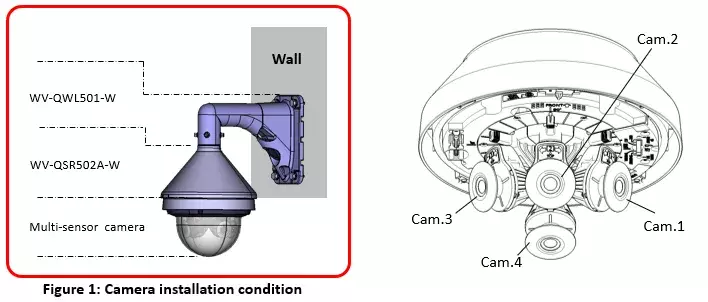
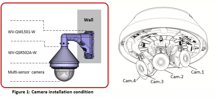
1. Installation condition of WV-X8571N / WV-S8531N :
- Cam.1, 2 and 3 are arranged horizontally / Camera 4 is tilted downward (horizontal + downward layout)
- Installation height of the camera is 3 meter
- The camera is installed on the building wall as shown in Figure 1 below
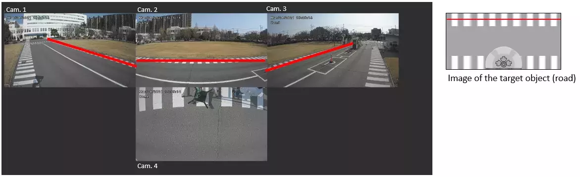
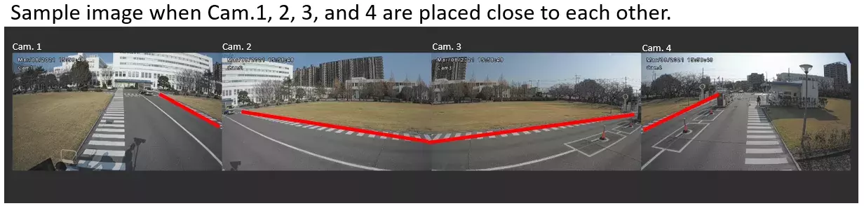
2. Before inclination (YAW) angle adjustment
The target object (road in this example) is tilted in Cam.1 and Cam.3 images as shown in the below red lines.
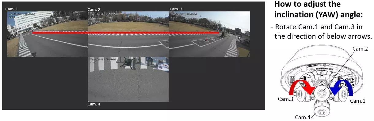
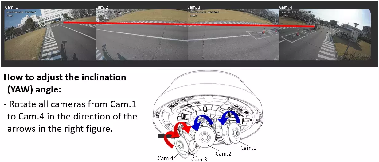
3. After inclination (YAW) angle adjustment
The target object (road in this example) above the center of the screen can be displayed horizontally as shown in the below red line.
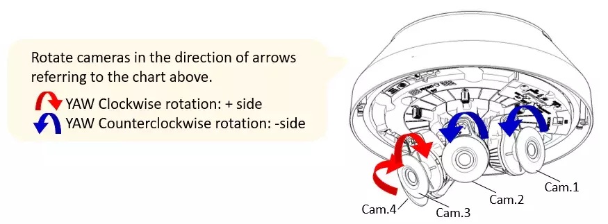
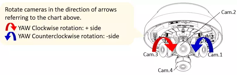
4. TILT/YAW angle adjustment - Reference chart
| Pattern | Cam. 2 | Cam. 1, 3 | Cam. 1 | Cam. 3 | Cam. 4 | ||
| TILT angle*1 (degree/ notch count) |
YAW angle (degree) |
TILT angle*1 (degree/ notch count) |
YAW angle*2 (degree/ notch count) |
YAW angle (degree) |
TILT angle*3 (degree/ notch count) |
YAW angle (degree) |
|
| 1 | 80 deg. / 0 notch | 0 deg. | 80 deg. / 0 notch | -10 deg. / 4 notch | 10 deg. | -15 deg. / 0 notch | 0 deg. |
| 2 | 75 deg. / 2 notch | 0 deg. | 80 deg. / 0 notch | -12.5 deg. / 5 notch | 12.5 deg. | -15 deg. / 0 notch | 0 deg. |
| 3 | 70 deg. / 4 notch | 0 deg. | 80 deg. / 0 notch | -15 deg. / 6 notch | 15 deg. | -15 deg. / 0 notch | 0 deg. |
| 4 | 65 deg. / 6 notch | 0 deg. | 80 deg. / 0 notch | -17.5 deg. / 7 notch | 17.5 deg. | -15 deg. / 0 notch | 0 deg. |
| 5 | 60 deg. / 8 notch | 0 deg. | 77.5 deg. / 1 notch | -22.5 deg. / 9 notch | 22.5 deg. | -15 deg. / 0 notch | 0 deg. |
| 6 | 55 deg. / 10 notch | 0 deg. | 77.5 deg. / 1 notch | -27.5 deg. / 11 notch | 27.5 deg. | -12.5 deg. / 1 notch | 0 deg. |
| 7 | 50 deg. / 12 notch | 0 deg. | 77.5 deg. / 1 notch | -32.5 deg. / 13 notch | 32.5 deg. | -7.5 deg. / 3 notch | 0 deg. |
| 8 | 45 deg. / 14 notch | 0 deg. | 75 deg. / 2 notch | -37.5 deg. / 15 notch | 37.5 deg. | -5 deg. / 4 notch | 0 deg. |
| 9 | 40 deg. / 16 notch | 0 deg. | 75 deg. / 2 notch | -40 deg. / 16 notch | 40 deg. | -2.5 deg. / 5 notch | 0 deg. |
| 10 | 35 deg. / 18 notch | 0 deg. | 75 deg. / 2 notch | -42.5 deg. / 17 notch | 42.5 deg. | 0 deg. / 6 notch | 0 deg. |
| 11 | 30 deg. / 20 notch | 0 deg. | 75 deg. / 2 notch | -47.5 deg. / 19 notch | 47.5 deg. | 5 deg. / 8 notch | 0 deg. |
Note: One notch is 2.5 degree for both TILT and YAW. A camera clicks every one notch as a guide.
Refer to the Additional Information “How to adjust the angle of view” for details.
*1 When the TILT end at horizontal position is 0-notch
*2 When the vertical position of YAW is 0-notch
*3 When the TILT end at downward position is 0-notch
Installation example #2 - horizontal layout
1. Installation condition of WV-X8571N / WV-S8531N :
- Cam.1, 2, 3 and 4 are arranged horizontally (horizontal layout)
- Installation height of the camera is 3 meter
- The camera is installed on the building wall as shown in Figure 1 below
2. Before inclination (YAW) angle adjustment
The target object (road in this example) is tilted in all images from Cam.1 to Cam.4 as shown in the below red lines.
3. After inclination (YAW) angle adjustment
The target object (road in this example) in the upper 30% of the screen can be displayed horizontally as shown in a red line.
4. TILT/YAW angle adjustment - Reference chart
| Pattern | Cam. 2, 3 | Cam. 2 | Cam. 3 | Cam. 1, 4 | Cam. 1 | Cam. 4 |
| TILT angle*1 (degree / notch count) |
YAW angle*2 (degree / notch count) |
YAW angle (degree) |
TILT angle*1 (degree / notch count) |
YAW angle (degree / notch count) |
YAW angle (degree) |
|
| 1 | 80 deg. / 0 notch | 0 deg. / 0 notch | 0 deg. | 80 deg. / 0 notch | -7.5 deg. / 3 notch | 7.5 deg. |
| 2 | 75 deg. / 2 notch | -2.5 deg. / 1 notch | 2.5 deg. | 80 deg. / 0 notch | -10 deg. / 4 notch | 10 deg. |
| 3 | 70 deg. / 4 notch | -5 deg. / 2 notch | 5 deg. | 80 deg. / 0 notch | -12.5 deg. / 5 notch | 12.5 deg. |
| 4 | 65 deg. / 6 notch | -7.5 deg. / 3 notch | 7.5 deg. | 80 deg. / 0 notch | -15 deg. / 6 notch | 15 deg. |
| 5 | 60 deg. / 4 notch | -10 deg. / 4 notch | 10 deg. | 80 deg. / 0 notch | -17.5 deg. / 7 notch | 17.5 deg. |
Note: One notch is 2.5 degree for both TILT and YAW. A camera clicks every one notch as a guide.
Refer to the Additional Information "How to adjust the angle of view" for details.
*1 When the TILT end at horizontal position is 0-notch
*2 When the vertical position of YAW is 0-notch